
Methods for Controlling Deformation in Thin-Walled Machining
The root cause of deformation in thin-walled CNC parts is insufficient material rigidity, which causes clamping force, cutting heat, and cutting force to shift or warp the workpiece. Common control methods include separating roughing and finishing, symmetric clamping design, low-pressure or vacuum fixtures, in-process stress relief, and three-stage inspection covering incoming material, in-process, and outgoing shipment. Buyers should provide wall thickness, length-to-diameter ratio, material, and heat treatment status at the RFQ stage so suppliers can assess whether the fixtures and cutting parameters can meet the tolerance requirements.
How Much Impact Does Fixture Design Have on Thin-Walled Part Deformation?
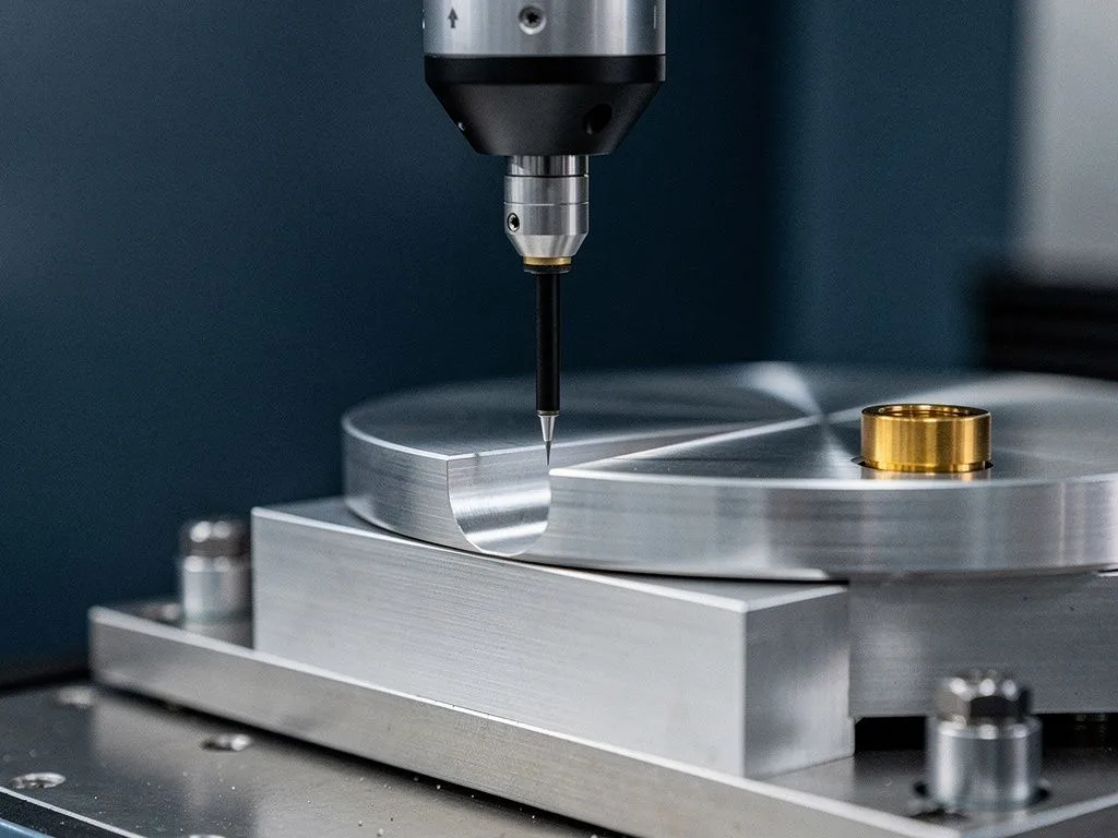
Fixture design directly determines the amount of deformation in thin-walled parts because clamping force itself is one of the sources of deformation. Traditional three-jaw or four-jaw chucks leave indentations on the outer diameter of thin-walled parts and distort roundness. Therefore, thin-walled parts often use symmetric clamping, radial support, vacuum fixtures, or low-pressure dedicated fixtures to distribute clamping force evenly. Swiss-type lathes, because the guide bushing is close to the cutting point, offer high rigidity and a short clamping section, which is especially advantageous for long, thin-walled parts. This is why Swiss-type machines like Star are often used for small precision thin-walled parts. Besides the chuck type, the clamping contact area and clamping direction also affect deformation. Radial clamping is more likely to collapse the thin-walled outer diameter than axial clamping, so many thin-walled parts switch to axial end-face clamping plates or internal expansion fixtures. Buyers should mark no-clamp zones and preferred datum surfaces on the drawing to give suppliers clear guidance when designing fixtures. As a next step, buyers can ask suppliers to provide fixture schematic diagrams and clamping force estimates as a technical review basis before sampling.
How do thin-wall deformation tendencies differ across materials?
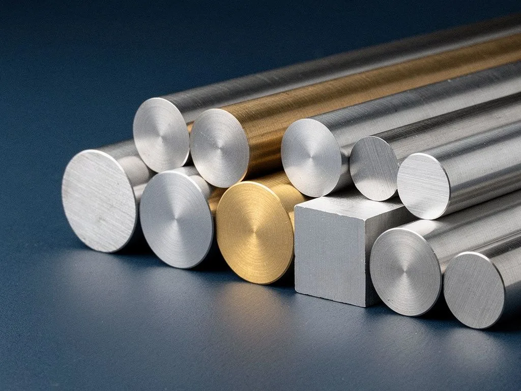
Aluminum alloys have low elastic modulus, dissipate heat quickly, but have a high coefficient of thermal expansion; thin walls tend to collapse near clamping points, and dimensions drift with temperature after machining. Stainless steel has higher rigidity but a pronounced work-hardening tendency; heat accumulation causes thin-wall areas to warp. Carbon steel has moderate cutting resistance, and deformation in thin-walled parts mainly comes from clamping rather than heat. Brass and copper have excellent machinability but low rigidity, so thin-walled parts are prone to tool deflection errors during finishing. Each material requires a different clamping strategy and cutting parameters; one process cannot be applied to all materials. Buyers should provide tolerance requirements based on material characteristics rather than applying the same drawing to all materials. Yuan Shun Li has CNC turning, milling, mill-turn, and Swiss-type lathe processes, allowing the most suitable machining path to be selected based on material and part geometry. As a next step, buyers can specify material grade and heat treatment condition on the RFQ to avoid suppliers responding with generic processes.