ysl-cnc material-tolerance

What Are the Achievable Tolerance Limits for Common Metal Materials?

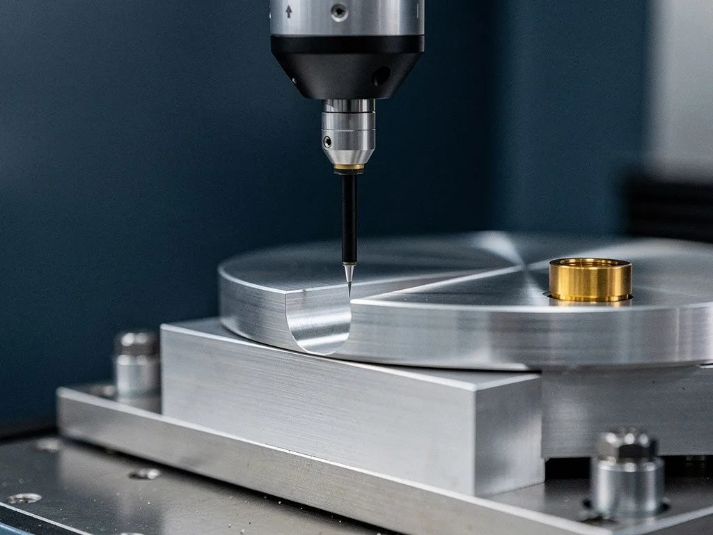
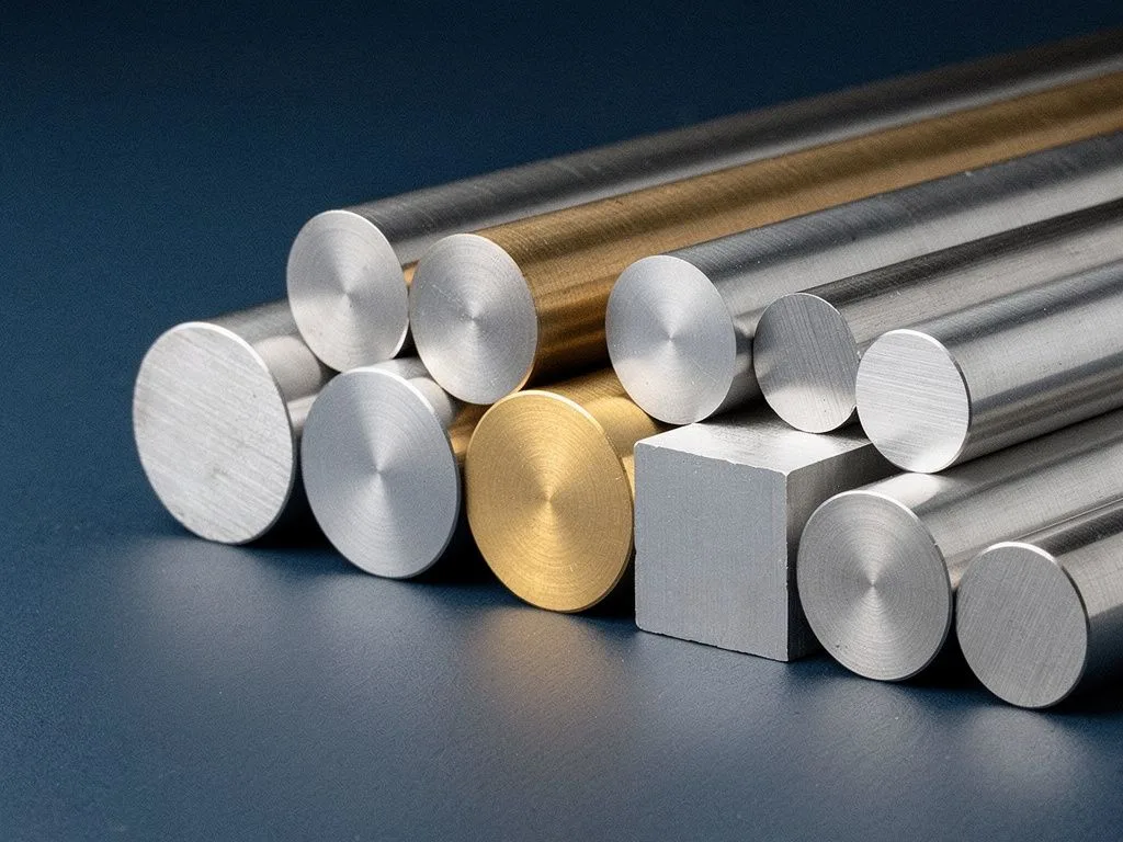
The achievable tolerance limits for common metal materials vary depending on the material itself, the machining method, part geometry, and measurement approach—there is no single number that applies to every situation. In general, CNC milling of aluminum alloys can achieve linear tolerances of ±0.01 mm to ±0.025 mm under standard conditions. Stainless steel and carbon steel, due to higher cutting resistance and differences in thermal expansion coefficients, typically require looser tolerances of ±0.02 mm to ±0.05 mm. Brass and copper, with their high ductility and low cutting resistance, can achieve tighter tolerances, but thin-walled parts and parts with high length-to-diameter ratios must still be confirmed against actual specifications. The true tolerance limit is determined by the combined result of material, tooling, fixtures, machine grade, and measurement equipment.
Key Takeaways

  • Tolerance limits vary by material

    CNC milling of aluminum alloys can achieve ±0.01 to ±0.025 mm, while stainless steel and carbon steel require looser tolerances of ±0.02 to ±0.05 mm. Brass and copper can hold tighter tolerances, but thin-walled parts and high length-to-diameter ratio parts must be confirmed against actual specifications.

  • Machining method affects tolerance capability

    CNC turning of aluminum alloys can achieve ±0.01 mm, while stainless steel is approximately ±0.02 mm. Milling is affected by tooling and fixtures. Swiss-type sliding headstock machines are suitable for slender parts. Choosing the right process is more important than forcing tighter tolerances.

  • Six factors determine achievable tolerances

    Material machinability, machine grade and repeat positioning accuracy, tool wear and cutting strategy, fixture design and workpiece rigidity, measurement equipment and methods, and ambient temperature and thermal stability together determine tolerance limits.

  • Surface and heat treatments change dimensions

    Surface treatments such as anodizing generate a 5 to 30 μm coating layer, and heat treatment can cause volume expansion and deformation. The drawing should specify when measurements are taken; otherwise, if the tolerance band is smaller than the coating thickness, dimensions will exceed specifications.

Why Do Achievable Tolerances Differ Across Metal Materials?

Achievable tolerances differ across metal materials primarily due to three variables: cutting resistance, thermal expansion coefficient, and material rigidity. Aluminum alloys are soft with low cutting resistance, resulting in low tool load and heat that is easily carried away with chips, allowing tighter tolerances on the same CNC machine compared to stainless steel. Stainless steel undergoes work hardening during machining, accelerating tool wear and concentrating heat at the tool-workpiece interface, causing localized thermal expansion and dimensional drift. Carbon steel falls between the two, but higher carbon content means higher hardness and a need for wider tolerance bands. Brass and copper, with excellent ductility, smooth cutting surfaces, and slow tool wear, are often chosen for tight-tolerance applications. For buyers, understanding material properties is the first step in judging whether drawing tolerances are reasonable, rather than simply demanding suppliers "make it as tight as possible."

How Do Tolerance Limits Differ Between CNC Turning, Milling, and Swiss-Type Lathes?

Tolerance limits for CNC turning, milling, and Swiss-type lathes differ due to machining principles and machine structure. CNC turning is suited for rotational parts; with sufficient rigidity, aluminum can achieve ±0.01 mm and stainless steel approximately ±0.02 mm in axial and radial dimensions. CNC milling (including 3-axis to 5-axis) handles prismatic or contoured parts, with tolerances affected by tool length, fixture rigidity, and cutting strategy; aluminum commonly achieves ±0.01 mm to ±0.025 mm, while stainless steel requires evaluation of whether rough and finish passes should be separated. Swiss-type lathes (Star) are designed for slender and small-diameter parts, where guide bushings maintain stable dimensions even for high length-to-diameter ratios, making them a common choice for medical, aerospace sensor, and electronic connector applications. For buyers, selecting the right machining method is more important than forcing a tolerance number; if a drawing specifies ±0.005 mm but the geometric features are not suited to that process, the actual dimensional spread in delivery will only be larger.

Six Key Factors Affecting Achievable Tolerances

  • Material Cutting Characteristics

    Aluminum and copper have low cutting resistance and can achieve tighter tolerances; stainless steel and carbon steel require looser tolerances due to hardening and thermal effects.

  • Machine Grade and Repeat Positioning Accuracy

    The rigidity and thermal compensation capabilities of equipment such as BROTHER, TAKISAWA, and Star directly affect tolerance limits.

  • Tool Wear and Cutting Strategy

    Separating rough and finish machining and managing tool life are key to maintaining batch consistency.

  • Fixture Design and Workpiece Rigidity

    Thin-walled and slender parts require special fixtures; otherwise, clamping deformation will consume the tolerance band.

  • Measurement Equipment and Methods

    The resolution of CMMs, profilometers, and roughness testers determines the tolerance level that can be verified.

  • Ambient Temperature and Thermal Stability

    Temperature differences between the workshop and measurement room can distort tolerances at the micrometer level.

material tolerance scene 1

How should tolerances be managed for thin-walled parts and parts with a high length-to-diameter ratio?

Tolerances for thin-walled parts and parts with a high length-to-diameter ratio must be reconsidered from the perspective of deformation control, rather than directly applying the tolerance grades used for solid parts. Thin-walled parts spring back after clamping and cutting stress is released; the thinner the wall, the greater the springback. A common practice is to split machining into roughing and finishing passes, leave a compensation allowance, and use vacuum fixtures or low-pressure clamping to reduce deformation. Parts with a high length-to-diameter ratio (length/diameter ratio exceeding 8:1) tend to vibrate during turning, causing periodic dimensional deviations. The guide bushing support of a Swiss-type lathe is a common solution. For buyers, if a drawing simultaneously specifies thin walls, tight tolerances, and strict geometric tolerances, it is essential to discuss the machining sequence and deformation compensation strategy with the supplier during the RFQ stage; otherwise, yield rates and costs will get out of control during mass production. The specific compensation allowance should be confirmed based on the actual specifications.
How do surface treatments and heat treatments change final tolerances?

Surface treatments and heat treatments change final tolerances because these processes add an additional layer of dimensional variation on top of the finished part dimensions. Surface treatments such as anodizing, nickel plating, and chemical conversion coatings generate a coating layer ranging from 5 μm to 30 μm on the workpiece surface. If the tolerance band is smaller than the coating thickness, the dimensions will fall out of specification. The impact of heat treatment is even greater: carburizing and quenching cause volume expansion, while the deformation direction of induction hardening and laser hardening is difficult to predict. Vacuum heat treatment deforms less but is still not zero. For buyers, the correct approach is to note on the drawing either "dimensions to be measured after heat treatment" or "allow for coating thickness before surface treatment," rather than requiring the supplier to simultaneously meet both the tolerance and the coating thickness on the final finished part. In practice, the compensation allowance for dimensional changes before and after heat treatment should be confirmed based on actual specifications and requires actual measurement during the trial production stage to be finalized.

material tolerance scene 2

What are common misunderstandings in geometric dimensioning and tolerancing (GD&T) callouts?

Common misunderstandings in geometric dimensioning and tolerancing (GD&T) callouts often lead to disputes between buyers and suppliers during the acceptance stage. The first misunderstanding is treating GD&T as "the tighter, the better." However, geometric tolerances such as true position, parallelism, and circular runout all have underlying assumptions about datums and measurement methods. Overly tight callouts cause manufacturing costs and yield rates to deteriorate sharply. The second misunderstanding is an unclear definition of the datum reference frame, which leads to the same part being measured with different results by different suppliers. The third misunderstanding is ignoring the difference between maximum material condition (MMC) and least material condition (LMC), which directly affects whether a part passes functional inspection. For buyers, GD&T callouts should reflect the functional requirements of the part, rather than copying foreign drawings without understanding the underlying logic. Reaching an agreement with the supplier on datum definitions and measurement methods during the RFQ stage can save a significant amount of acceptance disputes later on.

What is the relationship between measurement uncertainty and tolerance zones?

The relationship between measurement uncertainty and tolerance zones determines whether a part can be objectively judged as "acceptable." The general principle is that the uncertainty of the measuring equipment should be less than 1/4 to 1/10 of the tolerance zone; otherwise, the measurement itself consumes part of the tolerance, causing the same part to yield different results in different measuring rooms. For example, if the accuracy of a coordinate measuring machine (CMM) is ±0.005 mm and the tolerance zone is only ±0.01 mm, the actual usable tolerance is reduced to ±0.005 mm, making mass production nearly impossible. For buyers, the correct approach is to specify the measuring equipment grade and uncertainty requirements on the drawing or in the technical specification, rather than just writing the tolerance numbers. Suppliers should use appropriate measuring equipment in all three stages—incoming inspection, in-process checks, and final inspection before shipment—and retain measurement records as a basis for quality traceability.

Frequently Asked Questions

What is the tolerance limit for CNC milling of aluminum alloys?

Under standard conditions, CNC milling of aluminum alloys can achieve linear tolerances of ±0.01 mm to ±0.025 mm. Actual achievable tolerances vary depending on part geometry, tooling, fixtures, and machine grade. Thin-walled parts or high length-to-diameter ratio parts require looser tolerances and must be confirmed against actual specifications.

Why are tolerances for stainless steel usually looser than for aluminum?

Stainless steel work-hardens during machining, tool wear accelerates, and heat concentrates at the tool-workpiece interface causing localized thermal expansion, which makes dimensions prone to drift. Therefore, tolerances typically need to be loosened to ±0.02 mm to ±0.05 mm. Aluminum is softer with lower cutting resistance, and heat is easily carried away with chips, allowing tighter tolerances.

How should tolerances be set for thin-walled parts and high length-to-diameter ratio parts?

Thin-walled parts and high length-to-diameter ratio parts must be considered from a deformation control perspective and cannot simply use solid part tolerances. Common practice for thin-walled parts is to use rough and finish machining in two stages, reserve compensation allowance, and use vacuum fixtures. For high length-to-diameter ratio parts (length/diameter ratio exceeding 8:1), Swiss-type sliding headstock machines with guide bushings can provide support and reduce vibration.

How do surface treatments affect final tolerances?

Surface treatments such as anodizing and nickel plating generate a coating layer of 5 μm to 30 μm on the workpiece surface. If the tolerance band is smaller than the coating thickness, dimensions will exceed specifications. The correct approach is to specify on the drawing that dimensions should reserve coating thickness before surface treatment, or require measurement after heat treatment.

What is the relationship between measurement uncertainty and tolerance band?

The uncertainty of measurement equipment should be less than 1/4 to 1/10 of the tolerance band; otherwise, the measurement itself will consume the tolerance. For example, if a CMM has an accuracy of ±0.005 mm and the tolerance band is only ±0.01 mm, the actual usable tolerance is only ±0.005 mm, making mass production nearly impossible. The drawing should specify the measurement equipment grade and uncertainty requirements.

Need an evaluation of achievable tolerances for a specific material and geometry?

Provide your part drawing, material, and tolerance requirements. We will evaluate achievable tolerances based on the process characteristics of CNC turning, milling, mill-turn, or Swiss-type lathe, and reply with initial feasibility and recommendations.