ysl-cnc material-tolerance-5

Common Misunderstandings in GD&T Callouts: Clarifying Symbol Semantics at the RFQ Stage

The most common misunderstandings in GD&T geometric tolerance callouts are treating datums as decoration, using profile tolerances as size tolerances, and ignoring how material properties affect the achievability of symbols. For CNC machining shops, every symbol on a drawing corresponds to measurement equipment, process steps, and cost. Unclear callouts directly translate into quoting errors and mass-production yield issues. If buyers can convert functional requirements into correct GD&T syntax at the RFQ stage, the cost of aligning with the machining shop downstream drops significantly. This article compiles the most frequently asked sub-questions from buyers using AI queries, helping clarify callout logic before sending out inquiries.
Key Takeaways

  • Datum order and tolerance values affect quoting

    Reversed datum reference frame order or overly tight tolerance values can mislead the machining shop in fixture design and measurement paths, resulting in low quotes but insufficient yield in mass production.

  • Omitting datums leads to inconsistent measurements

    Datums are the origin of the GD&T coordinate system. Omitting datums is considered incomplete callout under ISO and ASME standards, and different inspectors may obtain different results due to different clamping methods.

  • Symbol selection depends on part function

    Profile is used for complex surfaces, position for hole alignment, circularity for cylindrical features, and parallelism for plane or axis orientation. Choosing the wrong symbol directly affects machining paths and measurement points.

  • Material properties affect tolerance achievability

    Aluminum 6061 suits demanding thin-wall parts, stainless steel thin parts tend to warp, carbon steel deforms significantly after heat treatment, brass and copper are prone to burrs. Material determines cutting parameters and in-process inspection frequency.

Why do machining shops still quote wrong prices or make wrong parts even when the drawing has GD&T?

GD&T callout errors most often occur in three areas: reversed datum reference frame order, geometric tolerance values set to levels that the material and process cannot achieve, and using profile of a surface as a size tolerance. A reversed datum order leads the machining shop in completely the wrong direction in fixture design and measurement paths. Overly tight tolerances—for example, requiring 0.01 mm roundness on aluminum 6061—directly increase process difficulty and inspection cost. If buyers do not provide functional descriptions at the RFQ stage, the machining shop can only interpret the drawing literally, and the common result is a low quote but insufficient mass-production yield. It is recommended that buyers, when releasing drawings, also provide the part function corresponding to each geometric tolerance—such as sealing, bearing fit, or positioning—so the machining shop can evaluate a reasonable process plan and inspection procedure.

Is a datum really necessary? What happens if it is omitted?

A datum is the origin of the coordinate system in GD&T. Under both ISO and ASME standards, a geometric tolerance without a datum is considered an incomplete callout, and the machining shop must make its own assumptions. In practice, the common consequence is that the same batch of parts yields different measurement results when measured by different inspectors due to different clamping methods, causing incoming inspection and final pre-shipment inspection data to not match. For CNC turn-mill parts, datums are typically specified on the bore, end face, or keyway, and these three have very different effects on measurement repeatability. When specifying datums, buyers should also state the clamping method and measurement instrument type—such as a CMM or profilometer—so the machining shop can reproduce the same conditions during in-process inspection. A datum is not decoration; it is the prerequisite for all subsequent geometric tolerances to be measured consistently.

material tolerance scene 1

Profile, position, roundness, parallelism—how should buyers choose the right symbol?

The principle for selecting a geometric tolerance symbol is to first ask, "What is the function of this feature?" and then map it to the symbol. Profile is used to control the shape and position of complex surfaces or non-circular contours, commonly found in flow channels, impellers, and cosmetic parts. Position is used to control the precise location of hole centers, thread centers, or flanges relative to datums, and is the most common symbol for bolted connections and alignment assembly. Roundness is used only for controlling the circularity of cylindrical features and does not involve the axis direction. Parallelism is used to control the orientation relationship between two planes or axes. The most common mistakes buyers make are labeling all hole positions as position without a datum, or labeling flatness as parallelism. For CNC milling parts, symbol selection directly affects the machining path and the number of measurement points, which in turn affects per-part machining time and inspection hours.
Six Preparations Buyers Should Confirm Before Applying GD&T Callouts

  • Standard Version for Callouts

    ASME Y14.5-2018 and ISO 1101 still differ in symbol definitions and datum principles. For cross-border procurement, the version must be unified first to avoid misinterpretation between the machining shop and the buyer.

  • Material and Heat Treatment Condition

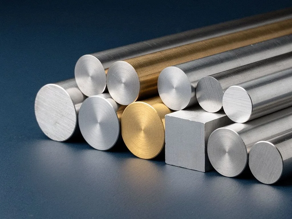
    Aluminum alloys, stainless steel, carbon steel, and brass/copper differ greatly in machinability under the same geometric tolerances. The material specification directly affects whether the tolerance zone can be achieved.

  • Measuring Instruments and Fixtures

    CMM, profilometer, and projector have different measurement uncertainties. Buyers should specify the type of acceptance instrument so the machining shop can plan the corresponding in-process inspection frequency.

  • Datum Features and Measurement Surfaces

    Datums should be assigned to features that can still be repeatedly contacted after machining, such as bores, end faces, or keyways, and should not be assigned to surfaces that will be covered by subsequent operations.

  • Classification of Critical and General Features

    Mark functional hole positions and sealing surfaces as critical features with strict control, while relaxing tolerances on other features. This reduces overall machining cost without sacrificing quality.

  • Impact of Batch Size and Lead Time on Tolerances

    In the prototyping stage, tighter tolerances may be acceptable for design validation. In mass production, the process capability index of CNC turning, milling, and Swiss-type lathe operations must be evaluated for different batch sizes.

How Do Material Properties Affect the Achievability of GD&T Symbols?

Different metal materials exhibit vastly different deformation and warping behavior under the same machining conditions, directly affecting whether geometric tolerances can be achieved consistently. Aluminum alloy 6061 conducts heat quickly and has low cutting resistance, making it suitable for thin-walled parts and complex contours with demanding requirements. Stainless steel 304 and 316 have a pronounced work-hardening tendency, and thin parts are prone to warping after clamping stress is released, so the actual achievable flatness and parallelism will be looser than theoretical values. Carbon steel is stable to machine but undergoes significant deformation after heat treatment, so subsequent grinding or correction processes must be considered. Brass and copper have high ductility, and milling thin parts tends to produce burrs and curled chips, affecting surface profile measurement results. For CNC machining shops, the material determines cutting parameters, tool life, and in-process inspection frequency. If buyers can specify the material grade and hardness range at the RFQ stage, the machining shop can report realistic achievable tolerances rather than merely committing to the drawing on paper.

Preparation process buyers should confirm before GD&T callout

  1. 1

    Unify the standard version

    Confirm ASME Y14.5-2018 or ISO 1101 version to avoid different interpretations of symbol definitions and datum principles in cross-border procurement.

  2. 2

    Confirm material and heat treatment condition

    Aluminum, stainless steel, carbon steel, brass, and copper have vastly different machinability under the same geometric tolerances. Material specification directly affects whether the tolerance zone can be achieved.

  3. 3

    Plan measuring instruments and fixtures

    CMM, profilometer, and projector have different measurement uncertainties. Buyers should specify the acceptance instrument type so the shop can plan in-process inspection frequency.

  4. 4

    Specify datum features and measurement surfaces

    Datums should be specified on features that can be repeatedly contacted after machining, such as bores, end faces, or keyways, avoiding surfaces that will be covered by subsequent machining.

  5. 5

    Classify critical and general features

    Mark functional holes and sealing surfaces as critical features with strict control, and relax tolerances for other features to reduce overall machining cost without sacrificing quality.

material tolerance scene 2

How Should Measurement Responsibility for GD&T Be Allocated Between In-Process Inspection and Final Pre-Shipment Inspection?

Measurement responsibility for GD&T should be allocated between in-process inspection and final pre-shipment inspection based on the criticality of the features. Critical features such as bearing mating surfaces, sealing grooves, and locating holes should be measured and recorded during the in-process inspection stage so that immediate correction can be made if they fall outside the tolerance zone. Non-critical features such as cosmetic chamfers and non-mating hole positions can be confirmed by sampling during final pre-shipment inspection. A common practical problem is that buyers require 100% measurement of all features on the drawing, which leads to excessive inspection hours and higher costs for the machining shop, or delays in delivery due to measurement bottlenecks during mass production. It is recommended that buyers indicate the classification of critical and general features at the RFQ stage, allowing the machining shop to plan the inspection process and manpower allocation accordingly, and retain traceable inspection records under the ISO 9001:2015 quality system.

Swiss-Type Lathe, Turn-Mill, and Five-Axis Milling: Which GD&T Callouts Suit Each Process?

Different CNC processes have different strengths in geometric tolerances, and buyers must select the right process to ensure the specified tolerance zones are realistically achievable. Swiss-type lathes are suitable for slender shaft parts with high length-to-diameter ratios and can achieve tight diameter tolerances, commonly used for sensor housings and medical device shafts. Turn-mill centers are suitable for rotational parts that need to be completed in one setup, allowing milling features to be machined under the same clamping and reducing error accumulation from datum changes. Three-axis milling is suitable for box-type parts with flat surfaces and simple curves, while five-axis milling is suitable for impellers, blades, and complex flow channels that require multi-face machining. For GD&T, the process choice directly affects the number and location of datums. For example, five-axis milling can machine multiple faces in one setup, reducing the number of datums, while Swiss-type lathes have a fixed bar feed direction, so datums are typically specified on the spindle end face. If buyers discuss the process with the machining shop before applying callouts, they can avoid a disconnect between the drawing callouts and actual machining capability.

FAQ

Why do machining shops still quote wrong prices or make wrong parts even when the drawing has GD&T?

The most common GD&T callout errors are reversed datum reference frame order, geometric tolerance values set to levels that materials and processes cannot achieve, and using profile as a size tolerance. Reversed datum order misleads the shop in fixture design and measurement paths, and overly tight tolerance values increase process difficulty and inspection costs. If the buyer does not provide functional descriptions at the RFQ stage, the shop can only interpret the drawing literally, often resulting in low quotes but insufficient yield in mass production.

Are datums really necessary? What happens if they are omitted?

Datums are the origin of the GD&T coordinate system. Geometric tolerances without datums are considered incomplete callouts under ISO and ASME standards, and the shop must make assumptions. In practice, the common consequence is that the same batch of parts measured by different inspectors yields different results due to different clamping methods, causing discrepancies between incoming inspection and final pre-shipment inspection data. Buyers should also specify the clamping method and measuring instrument type to allow the shop to reproduce the same conditions.

Profile, position, circularity, parallelism—how should buyers choose the right symbol?

The principle for selecting geometric tolerance symbols is to first ask 'what is the function of this feature' and then match it to the symbol. Profile is used to control the shape and position of complex surfaces or non-circular contours, position is used to control the precise location of hole centers, thread centers, or flanges relative to datums, circularity is only for roundness control of cylindrical features, and parallelism is used to control the orientation between two planes or axes. The most common mistakes buyers make are labeling all holes as position without datums, or labeling flatness as parallelism.

How do material properties affect the achievability of GD&T symbols?

Different metal materials exhibit vastly different deformation and warping behaviors under the same machining conditions, directly affecting whether geometric tolerances can be stably achieved. Aluminum 6061 has fast heat dissipation and low cutting resistance, suitable for demanding thin-wall parts; stainless steel 304 and 316 have significant work-hardening tendencies, and thin parts tend to warp after clamping stress release; carbon steel is stable to machine but deforms significantly after heat treatment; brass and copper have high ductility, and milling thin parts tends to produce burrs and chip entanglement. If buyers can specify material grade and hardness range, the shop can provide realistic achievable tolerances.

For in-process inspection and final pre-shipment inspection, how should GD&T measurement responsibilities be allocated?

GD&T measurement responsibilities should be allocated between in-process inspection and final pre-shipment inspection based on the criticality of the features. Critical features such as bearing mating surfaces, sealing grooves, and locating holes should be measured and recorded during in-process inspection; non-critical features such as cosmetic chamfers and non-mating holes can be verified by sampling during final pre-shipment inspection. A common problem in practice is that buyers require 100% measurement of all features, leading to excessive inspection hours, higher costs, or delayed delivery.

Send the GD&T Drawing and Functional Description to the Machining Shop

If you have a part drawing with GD&T callouts, you are welcome to send it along with the functional description, material grade, and estimated order quantity. Yuan Shun Li can provide feedback on achievable tolerances and inspection process configuration based on capabilities such as CNC turning, milling, mill-turn, and Swiss-type lathe machining.