
Which Geometric Features Cannot Be Produced on a 3-Axis Machine
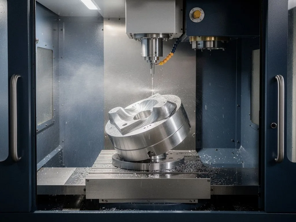
A 3-axis CNC milling machine can only move in the three linear directions X, Y, and Z, and the tool orientation is always parallel to the spindle. As a result, it cannot reach inclined surfaces, deep cavity walls, or complex curved surfaces on a workpiece in a single setup. When a part has multi-angle holes, undercuts, continuous curved surfaces, or complex contours that need to be completed in one operation, a 3-axis machine hits its limits and must be upgraded to 4-axis or 5-axis machining. The key criterion is not how complex the part looks, but whether the tool can contact all surfaces to be machined at the correct angle in a single setup.
Key Takeaways
3-axis machines can only perform linear machining
A 3-axis milling machine can only move in the three linear directions X, Y, and Z. The tool orientation is always parallel to the spindle, making it impossible to reach inclined surfaces, deep cavity walls, and complex curved surfaces in a single setup.
Multi-angle hole positions require 5-axis machining
When parts have multi-angle holes, undercuts, continuous curved surfaces, or complex contours that need to be completed in one operation, 3-axis machines hit a bottleneck. An upgrade to 4-axis or 5-axis machining is necessary.
The key criterion is tool contact
The deciding factor is not how complex the part looks, but whether the tool can contact all surfaces to be machined at the correct angle in a single setup.
Why 3-Axis Milling Cannot Machine Inclined Holes and Multi-Angle Hole Patterns
On a 3-axis milling machine, the tool can only feed along the spindle direction, so it can only machine holes that are perpendicular or parallel to the workpiece's reference planes. When a buyer's part drawing specifies multi-angle holes such as "hole axis at 30° to datum A and 15° to datum B," a 3-axis machine must rely on tilting fixtures or repositioning to machine them. Each repositioning accumulates positioning error, and the true position between holes often falls outside the tolerance zone. Multi-angle holes are common in flow connectors, hydraulic valve blocks, medical device housings, and aerospace structural parts. Even if such parts are forced through on a 3-axis machine, the multiple setups often cause datum drift and lead to scrap. The evaluation is straightforward: if the drawing requires position tolerance for two or more holes that are not on the same plane, you should directly consider 5-axis machining rather than trying 3-axis first and then reworking.
Why Deep Cavities and Undercuts Require 5-Axis Side Milling
When milling deep cavities on a 3-axis machine, the tool must be longer than the cavity depth to reach the bottom, but long tools lack rigidity and tend to vibrate, leaving unacceptable tool marks on the side walls or even breaking. Undercuts are areas on the workpiece that are shielded by the side geometry; a 3-axis tool cannot enter them from the front because its direction is limited. These features are common in valve parts, fluid connectors, impellers, blades, and cooling channels in plastic molds. When buyers receive such parts, they can first look at the section view in the drawing: if the cavity depth is more than four times the hole diameter, or if the side wall has an obvious hooked profile, a 3-axis machine will struggle to complete it in one operation even with special tools. 5-axis machining tilts and rotates the tool angle, allowing short tools to enter deep cavities and undercut areas via side milling, combining rigidity with surface quality.

Limitations of 3-Axis Machining for Compound and Free-Form Surfaces
Compound surfaces are surfaces where curvature changes in more than one direction simultaneously, such as blades, turbines, bone-contact surfaces of medical implants, and irregular tubing used in fluid analysis. 3-axis milling can only use ball-end mills to approximate the surface layer by layer through contour milling or pencil milling. The stepover of each pass leaves visible tool marks on the surface, and extensive hand polishing is required afterward to achieve functional surface roughness. This is unacceptable for aerospace blades, medical-grade implants, and optical components, because surface waviness directly affects airflow, cell adhesion, or optical performance. 5-axis machining allows the tool to feed along the surface normal direction, resulting in uniform stepover and consistent surface texture, and in many cases eliminates the need for subsequent polishing. The evaluation principle: when the surface curvature radius is less than three times the tool radius, or when the surface roughness requirement is below Ra 0.8 μm, the machining quality of a 3-axis machine is usually insufficient.
Why Complex Contours Should Be Completed in a Single Setup Instead of Multiple Clampings
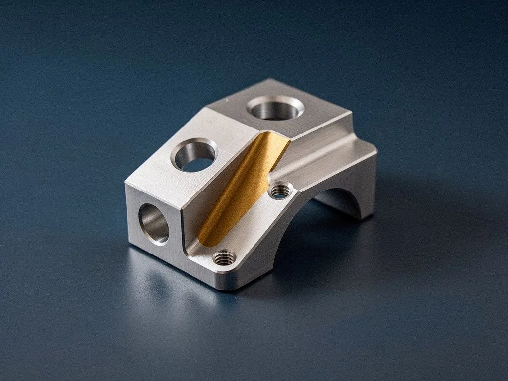
When machining complex parts on a 3-axis machine, the common practice is to flip the workpiece and clamp it again to machine features on the other side. However, each flip introduces new positioning errors, and the relative positional accuracy between the two faces is cumulatively amplified—a fatal flaw for precision parts. For example, an aluminum connector body has six hole positions distributed across three different directions. A 3-axis machine requires three separate clampings to complete the job. With a positioning error of 0.02 mm per clamping, the cumulative deviation between hole positions after three setups can exceed 0.05 mm, far beyond the ±0.02 mm tolerance specified on the drawing. 5-axis machining uses a rotary and tilting table to complete all features in a single setup, so the datum does not shift and positional accuracy is maintained. For buyers, multiple clampings also extend lead times and increase labor costs. The total machining time for a 5-axis single-setup process is often shorter than a 3-axis multi-clamping process.
Quick Drawing Review Process for Buyers
- 1
Check for multi-angle hole positions
Confirm whether there are two or more holes on different planes that need to maintain position tolerance.
- 2
Check for deep cavities and undercuts
In the section view, check for deep cavities with depth exceeding four times the hole diameter, or side walls with undercut contours.
- 3
Check for compound surfaces
Check for compound surfaces with curvature radius less than three times the tool radius.
- 4
Check for irregular holes
Check for irregular holes with non-circular cross-sections.
- 5
Confirm setup requirements
Check if the drawing specifies 'complete in one setup' or 'no multiple positioning'.

The 3-Axis Blind Spot for Irregular Holes and Special Thread Holes
Irregular holes refer to non-circular cross-section holes, such as D-shaped holes, square holes, elliptical holes, star-shaped holes, and irregular thread holes. The contours of these holes require the tool to perform both circular motion and axial feed inside the hole. A 3-axis machine is limited by the tool orientation and cannot machine contours that are not parallel to the axis inside the hole. In practice, many buyers assume that 'irregular holes can be solved by EDM,' but EDM leaves a recast layer on the surface, which is unacceptable for medical devices, semiconductor equipment, and aerospace parts because the recast layer affects the material's fatigue strength and corrosion resistance. 5-axis machining can directly use form cutters or angled feed to complete the sidewall contours of irregular holes in a single operation, preserving the material's original metallurgical state. How to judge: if the hole cross-section on the drawing is not a standard circle and surface integrity is required, you should directly request a 5-axis quote.
How Buyers Can Quickly Determine the Need for 5-Axis from Drawings
Buyers do not need to be machining experts to quickly assess a drawing using a few simple features. Check the drawing in order: First, are there two or more hole positions on different planes that need to maintain positional accuracy? Second, does the cross-section view show a deep cavity with a depth exceeding four times the hole diameter, or sidewalls with undercut contours? Third, are there compound surfaces with a curvature radius less than three times the tool radius? Fourth, are there irregular holes with non-circular cross-sections? Fifth, does the drawing specify 'complete in a single setup' or 'no multiple positioning'? If two or more of these conditions are met, the risk of machining the part on a 3-axis machine is high, and you should directly evaluate 4-axis or 5-axis options. Yuan Shun Li is equipped with BROTHER 3-axis and 5-axis machines, Star Swiss-type lathes, and mill-turn composite equipment, allowing us to select the most suitable process based on the part's geometric features. Once the buyer provides the 3D file, our engineers can evaluate the most economical machining path.
Six Geometric Features That 3-Axis Cannot Produce
Multi-Angle Hole Positions
Hole axes are not on the same plane; 3-axis requires multiple flips and clampings, accumulating positional errors. 5-axis completes them in one setup.
Deep Cavity Inner Walls
When cavity depth exceeds four times the hole diameter, long tools lack rigidity and are prone to breakage. 5-axis side milling maintains tool rigidity.
Undercuts and Backdrafts
Shaded areas on the side of the workpiece cannot be accessed head-on by 3-axis tools. 5-axis tilting allows direct side milling.
Compound Surfaces
Free-form surfaces with a curvature radius less than three times the tool radius show obvious tool marks when machined layer by layer on 3-axis. 5-axis feed along the normal direction ensures stable quality.
Irregular Holes
Non-circular cross-section holes such as D-shaped, elliptical, or star-shaped cannot have sloped surfaces machined inside by 3-axis. 5-axis can form them in one operation.
Complex Contours in a Single Setup
Parts requiring high positional accuracy that must avoid multiple clampings. 5-axis completes all features in one setup, keeping the datum stable.
Frequently Asked Questions
Why can't a 3-axis milling machine machine inclined holes and multi-angle hole positions?
On a 3-axis milling machine, the tool can only feed along the spindle direction, so it can only machine holes that are perpendicular or parallel to the workpiece reference plane. When the drawing specifies multi-angle hole positions, a 3-axis machine must rely on tilting fixtures or repositioning. Each repositioning accumulates positioning errors, and the true position tolerance between holes often exceeds the tolerance band.
Why do deep cavities and undercut features require 5-axis side milling?
When 3-axis milling encounters deep cavities, the tool must be longer than the cavity depth to reach the bottom. However, long tools lack rigidity and are prone to vibration, leaving tool marks on the side walls or even breaking. Undercuts are shielded areas on the side of the workpiece that 3-axis tools cannot enter due to direction constraints. 5-axis machining tilts and swivels the tool angle, allowing shorter tools to enter deep cavities and undercut areas via side milling.
What limitations do 3-axis machines have with compound and freeform surfaces?
3-axis milling can only use ball-end mills to approximate the surface layer by layer using contour machining or pencil milling. The stepover of each pass leaves visible tool marks on the surface, requiring extensive manual polishing to achieve functional surface roughness. 5-axis machining allows the tool to feed along the surface normal direction, resulting in uniform stepover and consistent surface texture, often eliminating the need for subsequent polishing.
Why should multiple setups be avoided for complex contours that need to be completed in one operation?
When machining complex parts on a 3-axis machine, the common practice is to flip the part and re-clamp it. However, each flip introduces new positioning errors, and the relative position tolerance between the two faces is amplified cumulatively. 5-axis machining uses a rotating and tilting table, allowing all features to be completed in a single setup. The datum does not shift, so position tolerances can be maintained.
What are the blind spots of 3-axis machining for irregular holes and special thread holes?
Irregular holes refer to holes with non-circular cross-sections, such as D-shaped holes, square holes, elliptical holes, star holes, and irregular thread holes. The contours of these holes require the tool to perform simultaneous circular motion and axial feed inside the hole. 3-axis machines are limited by tool orientation and cannot machine contours that are not parallel to the axis inside the hole. 5-axis machining can use form cutters or angled feed to complete the side wall contours of irregular holes in a single operation.
Provide a 3D File for Engineers to Evaluate the Most Suitable Machining Process
If your part drawing matches any two of the above characteristics, we recommend providing a STEP or IGES 3D file directly. Our engineers at Yuan Shun Li will evaluate the most economical machining path among 3-axis, 4-axis, or 5-axis based on the geometric features, and will reply with the lead time and unit price.