ysl-cnc five-axis-4

How long does the lead time for five-axis machining programming and simulation typically take?

For five-axis machining, the lead time for programming and simulation verification usually falls within several working days. The actual duration depends on the complexity of the part geometry, whether multiple fixtures are required, the number of simulation iterations, and the CAM engineer's current schedule. Simple symmetrical parts can be completed in 1–2 working days, while complex free-form surfaces or thin-walled parts may take more than a week. Buyers should provide 3D drawings and tolerance requirements at the quotation stage to allow suppliers to give a reliable delivery date, rather than estimating based on verbal descriptions alone.
Key Takeaways

  • Lead time depends on multiple variables

    Five-axis machining programming and simulation lead time typically ranges from several working days; simple symmetrical parts take 1-2 days, while complex freeform surfaces or thin-walled parts may require more than a week.

  • Five-axis programming takes longer than three-axis

    Five-axis requires simultaneous control of five axes and calculation of tool tilt angles and interference. Tool paths for freeform parts like blades and impellers need repeated adjustments, making the workload far higher than three-axis machining.

  • Simulation verification cannot be omitted

    Simulation checks overcutting, collisions, and interference to avoid machine crashes and production halts, but simulation itself may account for 30-40% of total lead time, and even more for complex parts.

  • Buyer preparation can shorten lead time

    Providing complete 3D drawings, tolerances, and material information during inquiry, and completing internal review, can avoid repeated modifications by CAM engineers and significantly shorten lead time.

Why does five-axis machining programming take longer than three-axis?

Five-axis machining programming takes longer than three-axis because the tool vector must simultaneously control the X, Y, and Z axes plus two rotary axes. Engineers cannot simply plan 2D contours; they must also calculate the tool's tilt angle and interference at every instant in space. This means CAM engineers need to spend more time on tool posture planning, tool length compensation, and post-processor settings. For free-form parts such as blades and impellers, a single toolpath region may need to be adjusted multiple times to avoid overcutting and collision—workload that does not exist in three-axis machining. If buyers can provide a complete 3D model and tolerance zones, engineers can directly proceed to toolpath planning, saving the time of reverse modeling. In practice, three-axis parts mostly only require setting the Z-axis retract and approach, while five-axis parts require specifying tool tilt angles and rotary axis limits segment by segment. This is also why the delivery time for the same workpiece can differ significantly. As a next step, buyers can proactively ask which CAM software the supplier uses and whether the post-processor has been verified for specific machines, as these factors affect the stability of the program output.

Why is simulation verification an indispensable step in five-axis machining?

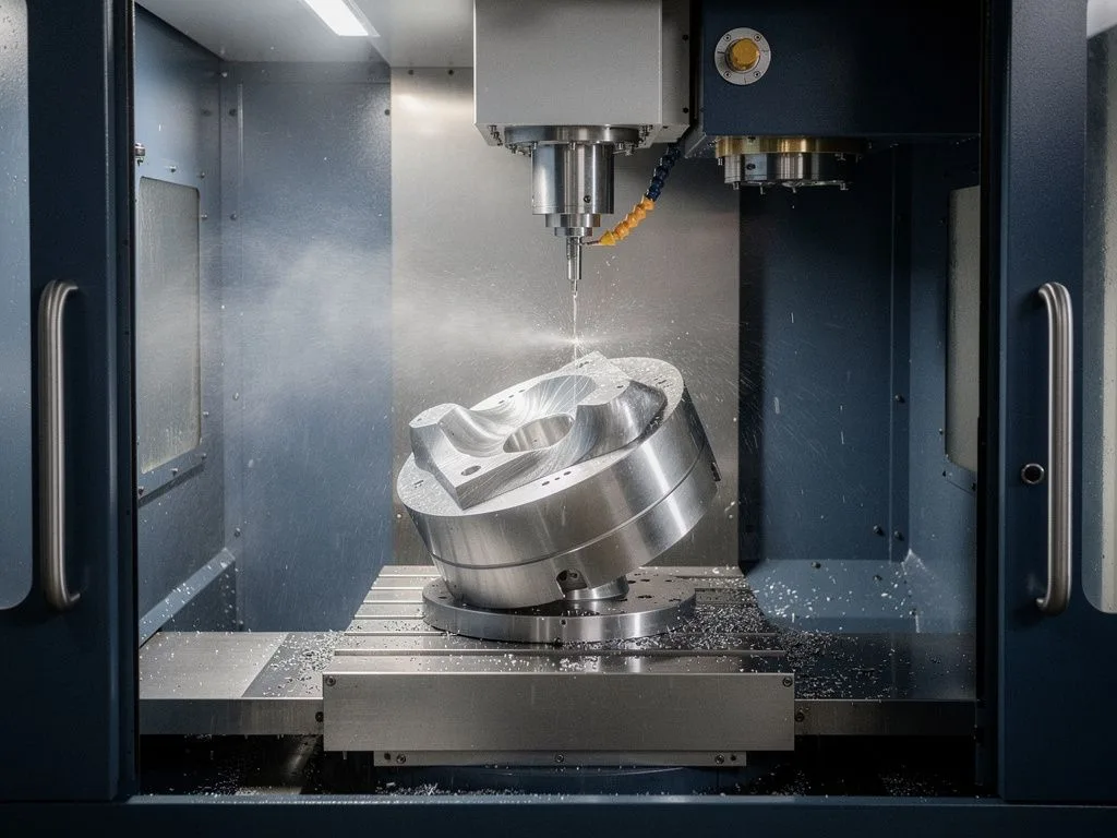
Simulation verification is an indispensable step in five-axis machining because during the movement of the rotary axes, the tool, tool holder, and fixtures are highly prone to collision. At best, this damages the workpiece; at worst, it causes a machine crash and halts production. The simulation function in CAM software checks each segment of the toolpath for overcutting, tool-fixture interference, and compares the actual cutting amount against preset values. For buyers, this means the supplier has already filtered out most risks before shipment, but it also reflects in the lead time. Generally, simulation itself may account for 30–40% of the total lead time, and even more for complex parts. When requesting a quote, buyers can proactively ask about the simulation method and software as a basis for evaluating the supplier's maturity. Simulation is not just about viewing the toolpath; the entire machine's motion envelope, fixture solids, and measurement probes must also be imported to fully recreate the real cutting scenario. If buyers find that a supplier only performs 2D wireframe simulation rather than 3D solid simulation, they should be cautious and request additional verification.

five axis scene 1

Which types of parts significantly extend the lead time?

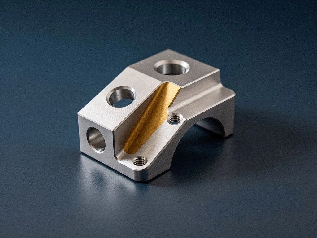
Part types that significantly extend lead time mainly include deep-cavity thin-walled parts, free-form impellers and blades, multi-face machining parts, and workpieces requiring multiple fixture changes. Deep-cavity thin-walled parts have low rigidity, so smaller cutting parameters and multiple light cuts must be planned, making the toolpath length potentially several times that of symmetrical parts. For impellers and blades, due to narrow channels and high twist, the tool tilt angle for each cut must be calculated individually. For multi-face machining parts that cannot be completed in a single setup, additional planning is required for the coordinate system and fixture configuration after flipping, all of which adds to the programming and simulation workload. If buyers can specify in advance whether the workpiece can be completed in one setup and whether multiple machining operations are allowed, it helps suppliers assess the lead time more accurately. In practice, aerospace structural parts, medical implant prototypes, and precision mold inserts are all types that tend to have longer lead times. As a next step, buyers can prepare similar parts' machining experience or failure cases to help suppliers avoid recurring problems in advance.
What external factors affect lead time?

Lead time is affected by CAM engineer scheduling, machine capacity saturation, tooling and fixture availability, and the number of drawing revisions from the buyer's side. CAM engineers are a scarce resource, and during peak seasons scheduling may be delayed by several days. If machines are simultaneously handling mass production orders, new part sampling will be pushed back. If tooling and special fixtures need to be purchased externally or customized, this also extends lead time. The most easily overlooked factor is drawing revisions from the buyer's side, as each revision requires the CAM engineer to rerun tool paths and simulations. If buyers can complete internal design reviews before sending drawings and designate a single point of contact, the risk of extended lead time can be significantly reduced. External factors also include post-processor compatibility issues, as different machine brands have different controller syntaxes. If a supplier maintains multiple machines, converting tool paths will also take additional time. Buyers can proactively ask suppliers about the brand and model of their primary machines as a reference for evaluating capacity and scheduling flexibility.

five axis scene 2

How should buyers prepare to shorten lead time?

To shorten lead time, buyers should provide complete 3D drawings (STEP or IGES format), 2D engineering drawings, material certificates, surface treatment requirements, and tolerance annotations at the quotation stage, and also state the urgency of delivery and whether partial shipments are acceptable. If the material is a special alloy, the heat treatment status should be communicated in advance to avoid the supplier discovering after programming that the hardness is too high and cutting parameters need adjustment. If tolerances involve GD&T geometric tolerances, the datum and symbols should be clearly marked on the drawing, not just described in the text field. If buyers can also provide past machining experience or failure cases of similar parts, it will help the supplier avoid pitfalls in advance, all of which will be reflected in shortened lead time. In practice, if buyers can conduct an internal review before sending drawings and finalize the version to a "machinable state," it can prevent CAM engineers from repeatedly modifying tool paths. As a next step, buyers can proactively ask suppliers whether they accept neutral file formats and whether a non-disclosure agreement is required, as these will affect whether lead time can start smoothly.

After lead time ends, how much longer does actual machining take?

After lead time ends, actual machining time varies depending on part volume, material, and cutting allowance, but is usually shorter than lead time. Small aluminum parts may be completed within hours, while large stainless steel or titanium parts may take several working days. Buyers should distinguish that "programming and simulation lead time" and "actual cutting time" are two separate schedules—the former is the engineer's work, the latter is the machine's work, and they cannot be conflated. If a supplier only gives a total number of days in the quotation, buyers should proactively ask how much each segment accounts for, in order to determine where there is room for compression in urgent orders. In practice, what can usually be compressed for urgent orders is actual cutting time, achieved through inserting orders, overtime, or dispatching idle machines. Lead time, on the other hand, involves the engineer's professional judgment, so the room for compression is relatively limited. As a next step, buyers can ask suppliers to provide segmented delivery milestones, such as "program completion date," "simulation approval date," and "first article completion date," to facilitate progress tracking.

Can programming and simulation for five-axis machining be done simultaneously?

In an ideal scenario, programming and simulation for five-axis machining can be done simultaneously, but in practice most suppliers still operate sequentially. The prerequisite for simultaneous operation is that the CAM engineer must import tool posture, fixture solids, and machine motion envelope into the simulation environment segment by segment while planning tool paths, which requires a high level of software proficiency. To avoid errors, most small and medium-sized suppliers still complete tool paths first and then perform simulation verification, which is one of the reasons lead time is difficult to compress. If a buyer encounters a supplier claiming to "complete simultaneously," they should further ask about the simulation software and verification process used, to confirm whether collision, overcut, and interference checks are truly covered. As a next step, buyers can ask suppliers to provide a sample simulation report as a basis for evaluating their maturity.

Six Key Variables Affecting Five-Axis Machining Lead Times

  • Part Geometry Complexity

    Features such as free-form surfaces, deep cavities, and thin walls significantly increase the number of toolpath planning and simulation iterations, making them a primary factor in extended lead times.

  • Fixturing and Workholding Design

    Whether the part can be machined in a single setup and whether custom fixtures are required directly determines how much time CAM engineers must spend on coordinate systems and interference checks.

  • CAM Software and Post-Processors

    Differences in post-processor settings across machine brands (e.g., TAKISAWA) affect the workload for toolpath output and simulation verification.

  • Material and Hardness

    Difficult-to-cut materials such as stainless steel and titanium alloys require more conservative cutting parameter planning, indirectly extending simulation and trial-cut verification time.

  • Tolerance and Surface Finish Requirements

    Tight tolerances and special surface finishes require additional in-process inspection and simulation, which buyers should clearly specify in advance.

  • Engineer Scheduling and Machine Capacity

    CAM engineer availability and machine scheduling are external variables; during peak seasons, lead times may extend by several working days compared to normal periods.

FAQ

How long does programming and simulation lead time typically take for five-axis machining?

It usually ranges from several working days. Simple symmetrical parts may be completed within 1-2 working days, while complex freeform surfaces or thin-walled parts may require more than a week, depending on part geometry complexity, number of fixtures, simulation iterations, and CAM engineer scheduling.

Why does five-axis programming take longer than three-axis?

Because five-axis machining requires simultaneous control of X, Y, Z axes plus two rotary axes. Engineers must calculate tool tilt angles and interference at every instant in space, spending more time on tool posture planning, tool length compensation, and post-processor settings. Tool paths for freeform parts like blades and impellers need repeated adjustments to avoid overcutting and collisions.

Why is simulation verification an indispensable step in five-axis machining?

Because during rotary axis movement, tools, tool holders, and fixtures are highly prone to collisions, which can damage the workpiece or cause machine crashes and production halts. Simulation checks overcutting, interference, and compares cutting volume segment by segment, filtering out most risks. However, simulation itself may account for 30-40% of total lead time.

Which part types significantly extend lead time?

Deep-cavity thin-walled parts, freeform impellers and blades, multi-face machining parts, and workpieces requiring multiple fixture changes significantly extend lead time due to low rigidity requiring multiple light cuts, individual calculation of tool tilt angles, and additional coordinate system planning for flipping. Aerospace structural parts, medical implant prototypes, and precision mold inserts fall into this category.

How should buyers prepare to shorten lead time?

During the inquiry stage, provide complete 3D drawings (STEP or IGES), 2D engineering drawings, material certificates, surface treatment requirements, and tolerance annotations. For special alloys, heat treatment status should be communicated in advance. GD&T tolerances must clearly indicate datums, and internal review should be completed before sending drawings to avoid repeated tool path modifications by CAM engineers.

Provide 3D Drawings for an Accurate Five-Axis Machining Lead Time Assessment

If you have five-axis machining requirements, please prepare 3D drawings, material specifications, and tolerance requirements, and contact us via the RFQ form. Yuan Shun Li will confirm the number of working days required for programming and simulation based on the actual specifications.