
How to Control Vibration and Deformation When CNC Turning Long, Slender Shafts
When CNC turning long, slender shafts (typically with a length-to-diameter ratio exceeding 10:1), vibration and deformation mainly originate from three sources: cutting forces, deflection due to the workpiece's own weight, and excessive tool overhang. Swiss-type lathes address this by using a guide bushing that supports the workpiece close to the cutting edge, combined with high spindle rigidity and stable tool dynamics, keeping vibration sources to a minimum. This makes them a common solution for precision parts with a length-to-diameter ratio above 20:1. Before placing orders with a Taiwanese CNC turning subcontractor, buyers should first confirm the workpiece's length-to-diameter ratio, clamping method, and roundness tolerance, then assess whether a Swiss-type lathe process is required.
Key Takeaways
Vibration is primarily caused by insufficient workpiece rigidity
When the length-to-diameter ratio exceeds 10:1, the workpiece's own weight and cutting forces induce deflection at the tool contact point, resulting in low-frequency chatter, high-frequency self-excited vibration, and secondary displacement from thermal deformation.
Swiss-type lathes suppress vibration with guide bushings
The guide bushing supports the workpiece close to the cutting edge, leaving almost no overhang in the cutting zone, making rigidity several times higher than conventional CNC lathes. This is a common solution for precision parts with length-to-diameter ratios above 20:1.
Three specifications determine vibration severity
Length-to-diameter ratio, final diameter tolerance band, and material cutting resistance determine the vibration problem; stainless steel exhibits significant work hardening and is the most common material that amplifies vibration.
Four documents must be prepared before placing an order
A complete 2D engineering drawing, 3D file, material specification, and estimated annual usage allow the contract manufacturer to assess the process without seeing a sample, avoiding specification mismatches after mass production.
Why Are Long, Slender Shafts Especially Prone to Vibration During Turning?
The main cause of vibration in long, slender shafts is insufficient workpiece rigidity: when the length-to-diameter ratio exceeds 10:1, the workpiece's own weight and cutting forces create deflection at the tool contact point, causing relative displacement between the tool and the workpiece. This relative displacement manifests in three forms—low-frequency chatter, high-frequency self-excited vibration, and secondary offset caused by thermal deformation. Aluminum alloy parts typically show smaller vibration amplitudes because the material is soft and cutting resistance is low; stainless steel and carbon steel, with higher cutting resistance, tend to amplify vibration more easily. If buyers provide only 2D drawings without specifying the length-to-diameter ratio and roundness tolerance, subcontractors often have to select machines based on experience, which frequently results in roundness exceeding specifications after mass production. It is recommended to list the workpiece's maximum length, minimum diameter, clamping section length, and roundness requirements during the RFQ stage, so the CNC turning shop can directly determine whether the Swiss-type lathe process is needed.

What Mechanism Does a Swiss-Type Lathe Use to Suppress Vibration?
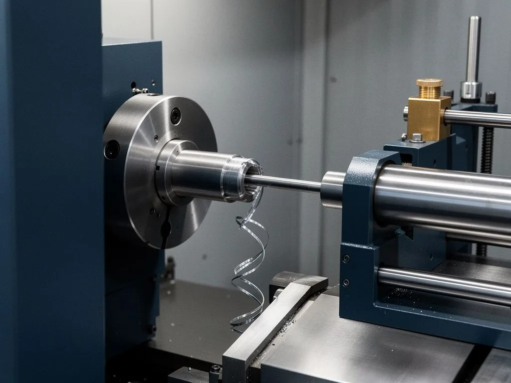
The core difference of a Swiss-type lathe lies in its guide bushing design: after the workpiece extends from the spindle end, it is fully supported by a movable guide bushing, with the distance between the bushing outlet and the cutting point typically only a few millimeters. This effectively places the support point right next to the cutting edge. With this structure, the workpiece has almost no overhang in the cutting zone, making its rigidity several times higher than that of a conventional CNC lathe, which naturally suppresses vibration. When a Star Swiss-type lathe is equipped with a synchronous guide bushing, the bushing rotates with the workpiece, further eliminating friction heat and runout between the bushing and the workpiece. For buyers, this means two things: first, at the same length-to-diameter ratio, a Swiss-type lathe can achieve more stable roundness and coaxiality than a conventional lathe; second, Swiss-type lathes have higher unit costs and longer per-piece machining times, so workpieces with a length-to-diameter ratio below 8:1 are not suitable for being forced through this process.

Which Workpiece Specifications Make Vibration Problems Particularly Severe?
The severity of vibration problems is determined by three specifications: length-to-diameter ratio, the tolerance band of the final diameter, and the material's cutting resistance. For workpieces with a length-to-diameter ratio exceeding 20:1, even with a Swiss-type lathe, additional control of cutting parameters (feed rate, depth of cut, spindle speed) is required to avoid chatter; for workpieces exceeding 30:1, back machining or multi-pass processing should be considered. If the final diameter tolerance requires ±0.01 mm or tighter, micro-displacement caused by vibration will directly show up as dimensional drift, so in addition to machine selection, tool path and clamping methods must also be reviewed. In terms of material, stainless steel (especially the 304 and 316 series) is the most common material for vibration amplification because its pronounced work hardening causes cutting resistance to rise as the tool wears; brass and copper, although soft, tend to cause built-up edge, which instead makes surface roughness unstable. If buyers can clearly specify these three specifications during the RFQ stage, the CNC turning shop can directly provide corresponding process recommendations.
In-Process Vibration Control Verification Flow
- 1
Incoming Material Inspection
Confirm material hardness and roundness meet the drawing requirements to prevent material variations from amplifying vibration.
- 2
In-Process Inspection
Measure workpiece roundness and coaxiality after rough machining; if a deviation trend is detected, immediately adjust cutting parameters or replace the tool.
- 3
Final Pre-Shipment Inspection
Use a CMM or optical projector to confirm finished dimensions, ensuring compliance with drawing specifications.

How can vibration control be verified during the manufacturing process?
Vibration control during manufacturing relies on a three-tier inspection system: incoming material inspection confirms that material hardness and roundness meet the drawing specifications, preventing material variations from amplifying vibration; in-process inspection measures the workpiece's roundness and coaxiality after rough machining, and if any deviation trend is detected, cutting parameters are immediately adjusted or the tool is replaced; final inspection before shipment uses a CMM or optical projector to confirm finished dimensions. For slender shaft parts, the frequency of in-process inspection is higher than for ordinary parts—many subcontractors sample-check roundness every 10 to 20 pieces and record tool life and cutting resistance. If the buyer commissions a CNC turning shop certified to ISO 9001:2015, the inspection process should have traceable written records, but the actual sampling frequency and measuring instrument specifications must still be confirmed at the ordering stage, because in-process inspection density varies significantly between manufacturers.
What information should buyers prepare before placing an order with a Taiwanese CNC turning subcontractor?
The most critical preparation before ordering is to enable the subcontractor to assess the process without seeing a sample. This requires four documents: a complete 2D engineering drawing (including tolerance zones and surface roughness symbols), a 3D file (STEP or IGES), material specifications (grade and hardness range), and estimated annual usage and batch size. If the drawing does not specify roundness, coaxiality, or runout tolerances, the subcontractor can only make assumptions based on experience, which often leads to specification mismatches discovered only after mass production. If the material specification only says "stainless steel" without specifying a grade, differences in work-hardening characteristics between batches will directly affect tool life and surface quality. Estimated annual usage affects the quotation structure—Swiss-type lathe programming setup costs are higher, and unit prices rise significantly when batch sizes are below 50 pieces. If the buyer can commit to long-term orders, there is much more room for price negotiation. Yuan Shun Li is located in the precision machinery cluster in Tanzi, Taichung, near the science park, offering geographical advantages for OEM parts supply and Tier-1 supplier prototyping needs, but specific lead times and capacity must still be confirmed based on actual specifications.
Six common measures for controlling vibration in slender shaft parts
Guide bushing support
Swiss-type lathes use a guide bushing to support the workpiece close to the cutting edge, reducing overhang to a few millimeters—the most direct method of vibration control.
Cutting parameter adjustment
Reducing depth of cut and feed rate while increasing spindle speed can reduce low-frequency chatter caused by cutting forces, but this extends machining time.
Tool geometry optimization
Selecting tools with large rake angles and sharp, small nose radii reduces cutting resistance; replace tools promptly upon wear to prevent resistance from increasing.
Reverse cutting
For workpieces with a length-to-diameter ratio above 30:1, feed the tool in from the tail end so that cutting forces do not act on the maximum overhang section.
Split machining
Separate roughing and finishing: roughing removes most of the material, while finishing leaves only a 0.1–0.2 mm allowance to minimize final deformation.
In-process roundness measurement
Sample-check roundness and coaxiality every 10–20 pieces, and adjust parameters immediately if a deviation trend is detected to avoid batch defects.
FAQ
Why are slender shaft parts particularly prone to vibration during turning?
The main cause of vibration in slender shaft parts is insufficient workpiece rigidity: when the length-to-diameter ratio exceeds 10:1, the workpiece's own weight and cutting forces induce deflection at the tool contact point, creating relative displacement between the tool and workpiece, manifesting as low-frequency chatter, high-frequency self-excited vibration, and secondary displacement caused by thermal deformation.
What mechanism do Swiss-type lathes use to suppress vibration?
The core difference of Swiss-type lathes lies in the guide bushing design: after the workpiece exits the spindle, it is fully supported by a movable guide bushing, with the distance between the bushing outlet and the cutting point only a few millimeters. This effectively brings the support point directly next to the cutting edge, leaving almost no overhang in the cutting zone, making rigidity several times higher than conventional CNC lathes.
Which workpiece specifications make vibration problems particularly severe?
The severity of vibration problems is determined by three specifications: length-to-diameter ratio, final diameter tolerance band, and material cutting resistance. When the length-to-diameter ratio exceeds 20:1, additional cutting parameter control is required; when tolerance requirements are within ±0.01 mm, vibration micro-displacement directly reflects in dimensional drift; stainless steel, due to its significant work hardening, is the most common material that amplifies vibration.
How can vibration control be verified during the manufacturing process?
Vibration control during the process is ensured through three layers of inspection: incoming material inspection confirms material hardness and roundness, in-process inspection measures roundness and coaxiality after rough machining, and final pre-shipment inspection uses a CMM or optical projector to confirm finished dimensions. The in-process inspection frequency for slender shaft parts is higher than for general parts, with sampling every 10 to 20 pieces.
What information should buyers prepare before placing an order with a Taiwanese CNC turning contract manufacturer?
The most critical preparation before placing an order is to enable the contract manufacturer to assess the process without seeing a sample. Four documents are required: a complete 2D engineering drawing (including tolerance bands and surface roughness symbols), a 3D file (STEP or IGES), material specification (grade and hardness range), and estimated annual usage and batch size.
Need to assess the feasibility of manufacturing slender shaft components?
Please provide 2D engineering drawings, 3D files, and material specifications. Yuan Shun Li will recommend the appropriate CNC turning process and inspection items based on the workpiece's length-to-diameter ratio and tolerance requirements.